ALARM MULTIPLEXOR 2
Case Studies
November 5, 2015
The client is one of the largest integrated power companies with a significant international presence. From Fuel and Logistics to Generation and Transmission to Distribution and Trading – exploring various renewable sources of energy in India and globally – it now has a significant presence in wind, solar, hydro, and geothermal energy space.
Requirement
Client’s one of the locations in Mumbai’s power generation unit has an alarm management system. In this system, Alarms from various parts of the plants are consolidated at various different servers and displayed on multiple screens to form a control room where decisions are taken based on the information received by means of alarms. In order to revamp the old alarm multiplexor system and reduce the number of screens where the alarms are displayed, the Client had decided to merge 5 server alarms to be received on one consolidated screen. The 5 systems are LCN, SER & Experion, Triconex, and MAX DNA systems.
Opportunity
Gauranga saw an opportunity to work with a prestige client and also be able to expand its offerings in Alarm Management systems. The five servers that were identified, worked on established operating systems and were very stable, which gave Gauranga the assurance of reliable alarms in the Proposed alarm management system. The interfaces to the various servers were standard buses like serial port bus and Ethernet port bus thus further strengthening the Gauranga design.
The Solution
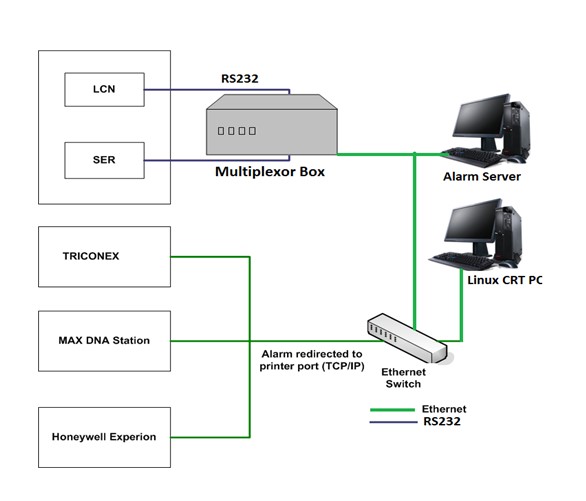
For this project, Gauranga implemented an Alarm Multiplexor system, where two of the five systems, which are serial ports, were integrated into a multiplexor hardware box, while the remaining 3 ports from servers will be collected through the Ethernet port. The beside picture shows the graphical representation of the proposed solution. The Multiplexor hardware box sent its data to the alarm server through an Ethernet port too. The alarm application, through the Socket application, will keep on receiving the stream of strings from the Multiplexor hardware. All the strings are parsed and stored in the database. Since it is socket communication, data won’t be lost. If by chance the application is closed, then Multiplexer will store the data internally. Once the connection is established Multiplexer will send the strings to this application. As seen in the figure beside, the LCN & SER ports were multiplexed by a hardware multiplexor box which was based on Linux operating system and Arm-based processor board. The Triconex, MAX DNA station, and Honeywell Experion servers were multiplexed through the Ethernet switch directly to the Alarm Server. The Windows-based application on the Alarm Server did the work of prioritizing the alarms to be displayed from all the three Ethernet-based and two multiplexed alarms stream from the multiplexor box. The Linux CRT PC is an optional PC in the system.

Resources
There are two types of resources required for the project
a) Intellectual resources
Intellectual resources required are people:
- Who designs the architecture of the entire system.
- Who takes care of the implementation aspects of each module which consists of the design of the hardware of the multiplexor box.
- Who does the firmware implementation of the Multiplexor BOX?
- Who implements the PC-based application which will present the live alarms, reports, history, and trends.
- At the client site, the client’s knowledgeable resources know how to operate the server and generate simulated alarms for testing purposes.
b) Computer resources
- Alarm Server PC with 2GB ram, 512MB Hard disk, Intel Pentium+ processor
- Multiplexor box with Linux-based Arm processor SBC board.
- Existing 5 Servers viz, SER, LCN, MAX DNA, Experion, Triconex.
c) Development tools
- Text editor for windows, IDE for development for Alarm Server application
- Compilers for Linux box and windows IDE
Process
The process includes the following steps:
- Proposal defining the high-level architecture diagram.
- Upon project approval, selection of the various components of the Multiplexor box. The Technologies TS-7300 board was selected as a motherboard for the alarm multiplexor box.
- Identify the hardware components of the Alarm Server PC.
- Design the protocol between the Multiplexor box and the Alarm Server.
- Design and develop the firmware for the Multiplexor box.
- Unit test the Multiplexor box firmware with simulated serial port software and Ethernet server-client software.
- Perform unit testing of connecting the Multiplexor box with the SER and LCN servers at the client end.
- Design and develop the Windows-based Application for the Alarm Server.
- Unit test the Windows application software with simulated data input on the Ethernet socket port to observe the alarms on the application’s user interface.
- Partial Integration testing of the Multiplexor box with the Windows Application on the Alarm Server, by sending serial simulated data to the multiplexor box to observe the alarms on the Alarm Server.
- Integration testing at the Client site with live serial port data from SER and LCN data to observe the alarms on the Alarm Server.
Integration testing further includes the data from the remaining three servers on the Ethernet channel to observe all the 5 servers data on the Alarm Server.
Facilitating Factors
- The team was given access to the 5 servers at the client’s end for the entire duration of the project as and when required, with a knowledgeable person from the client.
- Qualified Gauranga team for implementation of the Alarm Multiplexor box and the PC-based alarm server application.
Challenges Overcome
Communication with the SER & LCN servers, as they were serial ports with the unknown protocol was a challenge. It was solved by using a third-party application called portion, which enabled us to monitor the communication on the serial port in parallel to the running application. In this way, we were able to send commands to the SER and LCN ports and observe all the responses including the special characters/commands that are not received by the normal application as serial ASCII characters.
Results Observed
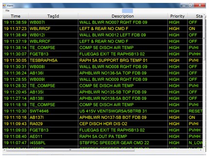
The alarm server application displayed rows of categorically colored alarms with multiple different columns showing details of the alarms. The picture below gives a glimpse of the alarm server application. This screen is reflected in the central screen of the control room.
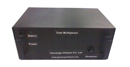
The alarm server is receiving alarms from all the five servers, two of which are through the Data Multiplexor box as described in the document above, whose picture is also shown below.


Lessons Learned
Use of a serial port background sniffer application must be used in the early stage of a project that involves a serial port, to save time and effort.
